

This tutorial will show you how to build your very own foam dart launcher robot using Viam, a Raspberry Pi, a generic foam dart launcher with foam darts, a USB camera, a solenoid, a relay, and a motor controller. This robot will be able to move around and launch foam darts.
This project is a great place to start if you are new to building robots, have a love for Nerf toys, an occasion to target something and launch a dart at it, or if you just want to troll your friends. Don’t forget to be careful and have fun!
What you’ll need for this tutorial
You will need the following hardware, software, tools, and consumables to complete this project:
IMPORTANT: If you use a different rover and/or motor component, ensure that the motor driver is compatible with the motors on your rover. For example, a brushed DC motor requires a brushed DC motor driver that is rated for the power requirements of the motor. Also, the configuration files shown in this tutorial must be modified if you use a different setup.
Hardware and software requirements
- Raspberry Pi with microSD card, with
viam-serverinstalled per our Raspberry Pi setup guide. - A wheeled rover
- A foam dart launcher
- A USB camera (webcam) (optional, to see where you are going and aiming)
- A solenoid
- A relay
- A dual motor controller If you use a different motor driver, refer to the manufacturer’s data sheet and our motor component topic to learn how to configure the pins.
- Jumper wires (breadboard wires)
Tools and consumables
- Solder (optional)
- Small flathead screwdriver
- Cutting pliers (flush-cutting pliers preferred)
- Electrical tape
- Elastic/rubber bands
How to assemble your hardware
Motor controller setup
A motor controller is a piece of hardware that takes digital signals from the Raspberry Pi and sends power to the motors accordingly. For this setup we have one dual motor controller for the two motors.
INFO: If you have more than two motors you will likely need two motor controllers.
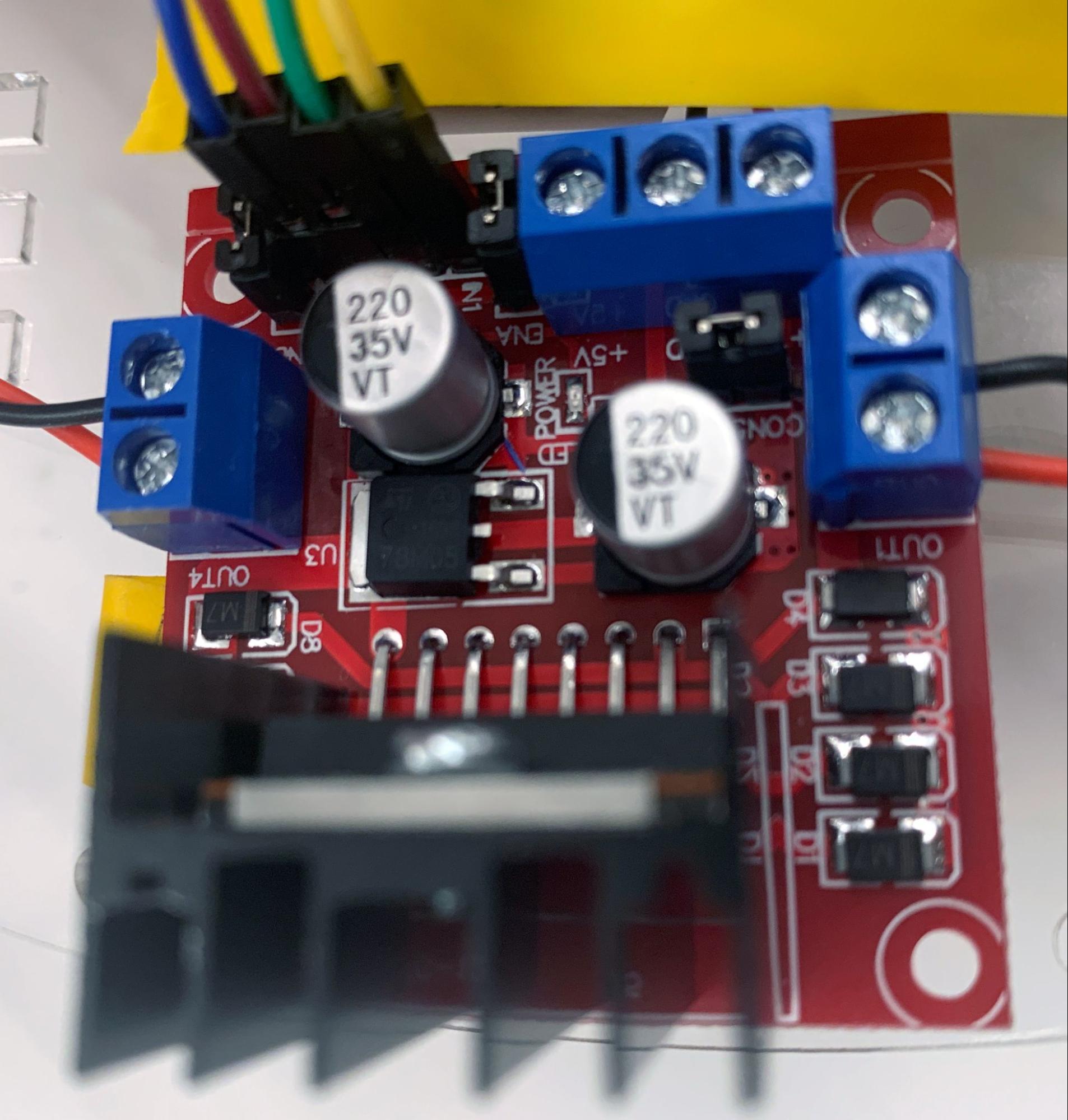
We need only worry about OUT1 through OUT4, IN1 through IN4, 12V, and ground.
- Attach left to the motor controller.
- Use a small flathead screwdriver to loosen the Out1 and OUT2 screw terminals.
- Place the red motor wire into OUT1
- Place the black motor wire into OUT2
- Use the flathead screwdriver to tighten the terminals to firmly hold the wires in place. Note: Tightly twisting each stripped wire end and then tinning it makes it easier to insert and secure the jumper in screw terminal connectors.
- Connect the control wires IN1 and IN2 to your Raspberry Pi.
- The example robot has IN1 -> pin 11, IN2 -> pin 13
- Repeat steps 1-2 for the right motor using OUT3, OUT4, IN3, IN4
- The example robot has IN3 -> pin 16, IN4 -> pin 18
- Connect the external power that will supply power to the motors.
- In the example we have 4 AA batteries connected to the motor driver giving us 6V of power for the motors.
Camera setup
This is as easy as plugging the camera into a USB slot on your Pi. We’ll configure the camera in the Viam app in later steps.
Relay/Solenoid setup
The solenoid component actuates the foam dart launcher trigger. The relay works as a switch to turn on and off the solenoid. This allows us to activate the foam dart launcher with a GPIO pin on the board.
INFO: We cannot directly power these components from GPIO pins, since there is a board limitation that restricts GPIO pins to providing 3.3V and a very limited current supply (16mA). Even the 3.3V and 5V power pins on the Pi supply are limited to about 1A. If a component attempts to pull more current than that, you risk power cycling the Pi. That is why we use a relay to supply 5VDC with a higher current to actuate the solenoid. This is standard practice for power control circuits in many situations. For example, by using a common off-the-shelf 15A light switch to actuate a relay bank, it is possible to control hundreds of amps of lighting for an entire office floor.
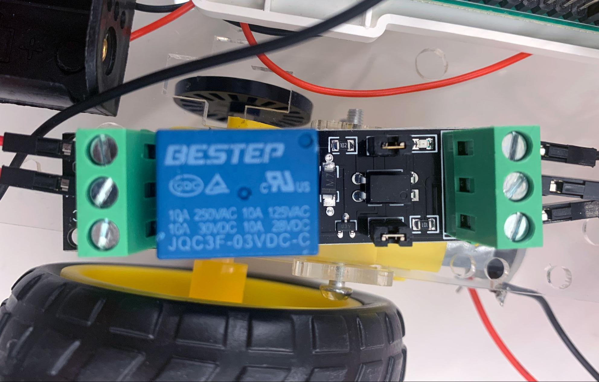
- Connect the solenoid to the relay.some text
- Connect a wire to the Normally Open (NO) terminal connector.
- Connect the other end to a ground pin on the Raspberry Pi.
- Connect the Relay COMmon pin.some text
- Connect the COM pin to the 3.3V power of the Raspberry Pi.
- Connect VCC (DC+) and ground (DC-) .some text
- Connect DC+ to the 6V of the external battery pack.
- Connect DC- to ground on the Raspberry Pi.
- Connect IN.some text
- Connect IN to a GPIO pin on the Raspberry Pi.
- For this example, we've connected to pin 37.
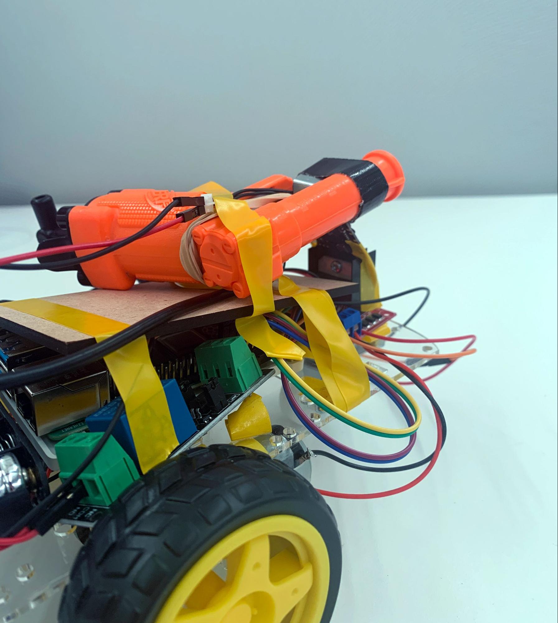
Assemble solenoid/foam dart launcher
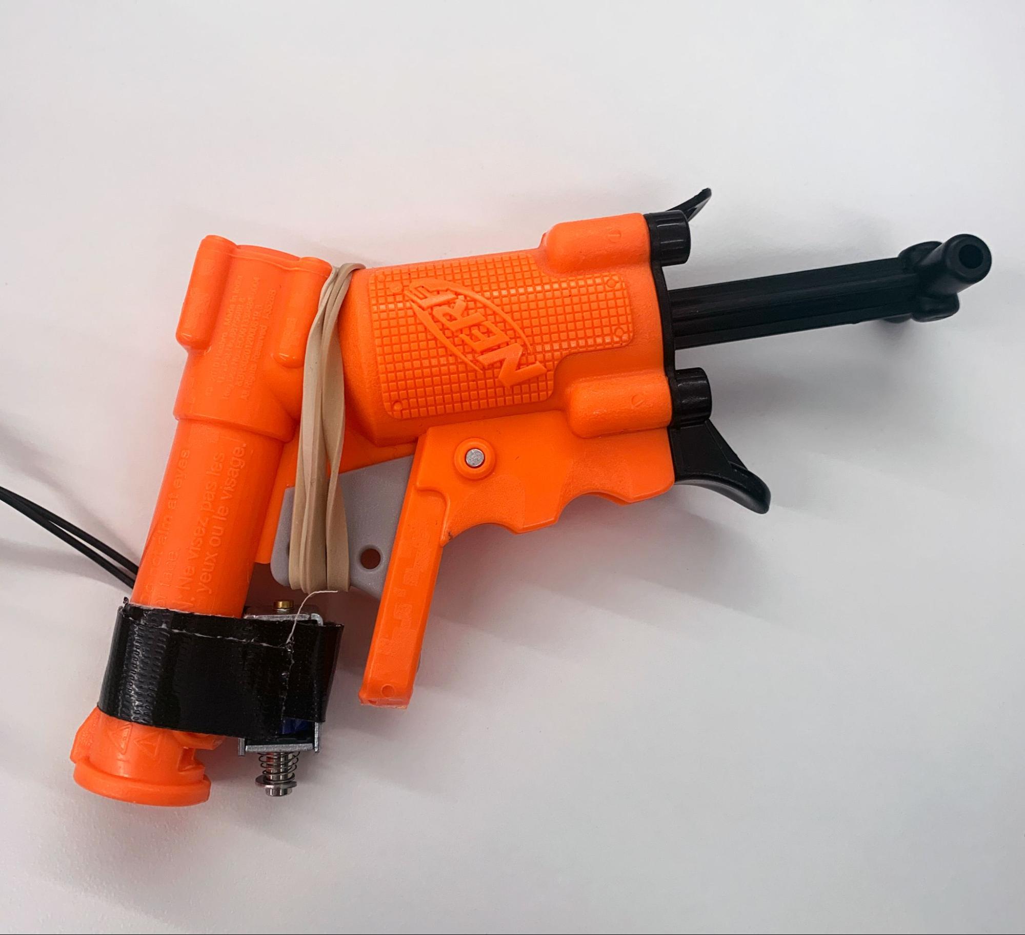
- Modify the foam dart launcher to make room for the solenoid. Using cutting pliers, we cut the trigger guard off of the front as seen in the picture above.
- Test that the solenoid has enough power to press the trigger when the foam dart launcher is loaded.
- If the solenoid is not strong enough we can:
- Wrap the trigger with rubber bands to make the trigger easier to activate.
- If you use the rubber band method, you may need to pull the rubber bands away from the trigger when reloading the foam dart launcher so it can reset and load properly. Try activating the solenoid manually to ensure that it hits the foam dart launcher trigger in the right spot.
- Increase the voltage to the solenoid. Right now it receives 5 volts, but some solenoids can support up to 12 volts. If necessary, you can connect the solenoid to another power supply such as a 9 volt battery. Check the details of your solenoid.
- If you choose to increase the voltage, you must connect VCC and ground (DC+ and DC-) to the new voltage source rather than connecting them to the Raspberry Pi as described in Step 3 of Assemble Solenoid/Foam Dart Launcher.
- Wrap the trigger with rubber bands to make the trigger easier to activate.
- Tape the solenoid in such a manner that it makes good contact with the trigger when activated with the relay.
- Attach all of your components to the base.
Configure your foam dart launcher robot with the Viam app
Add a new machine in the Viam app and give it a name. Then, follow the setup instructions to install viam-server and connect your Pi to the Viam app.
Board configuration (Raspberry Pi)
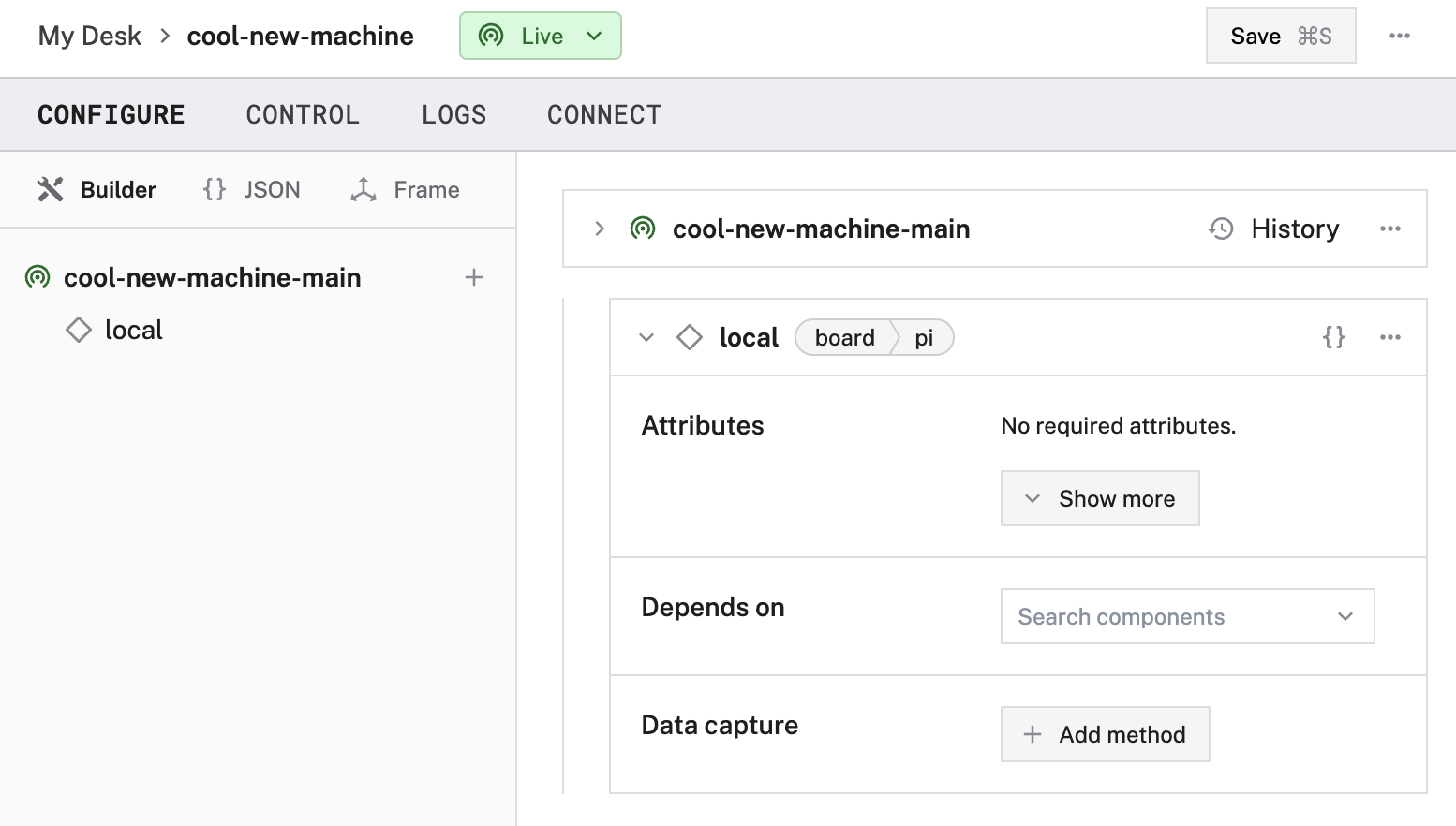
Add a board component to represent your single-board computer, which in this case is the Raspberry Pi. To create the new component, click the + icon next to your machine part in the left-hand menu and select Component. Select the board type, then select the pi model. Enter a name or use the suggested name for your board and click Create. We used the name "local". You can name your board whatever you want, just remember to use that name consistently in the following steps.
Your board component panel will look like this:
Motor configuration
Right motor
Click the + icon next to your machine part in the left-hand menu and select Component. Select the motor type, then select the gpio model. Enter right as the name and click Create.
Then from the Board dropdown, select local, the Raspberry Pi the motor is wired to.
Next, configure the Component Pin Assignment section to represent how the motor is wired to the board. In the Component Pin Assignment section of the right motor card, toggle the Type to In1/In2 to use the compatible mode for this motor driver. For A/In1 select 16 GPIO 23 and for B/In2 select 18 GPIO 24.
Click Show more and set max_rpm to 150. You can ignore the other optional attributes.
Left motor
Click the + icon next to your machine part in the left-hand menu and select Component. Select the motor type, then select the gpio model. Enter left as the name and click Create.
Then from the Board dropdown, select local, the Raspberry Pi the motor is wired to.
Next, configure the Component Pin Assignment section to represent how the motor is wired to the board. In the Component Pin Assignment section of the right motor card, toggle the Type to In1/In2 to use the compatible mode for this motor driver. For A/In1 select 11 GPIO 17 and for B/In2 select 13 GPIO 27.
Click Show more and set max_rpm to 150. You can ignore the other optional attributes.
Click Save at the top right of the screen.
Now that you have configured your motors, you can actuate them. Navigate to the Control tab.
You’ll see a panel for each configured component.
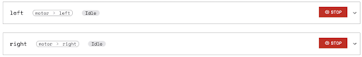
Click on the panel for the right motor.
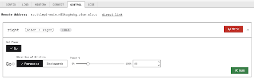
Now you can drive your left and right wheels separately. Let’s add a base to be able to control them together.
Base configuration
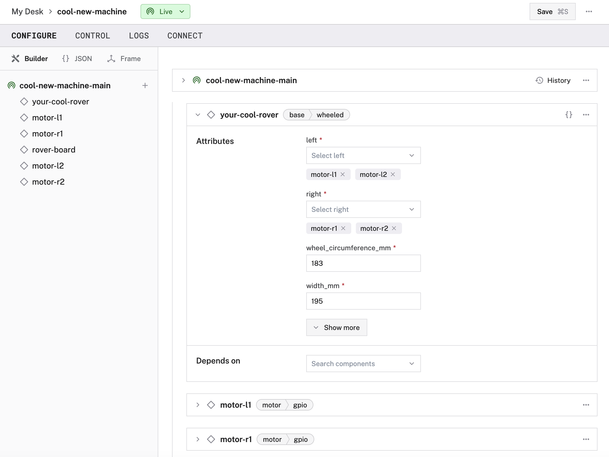
Next, configure the base component, which describes the geometry of your chassis and wheels so that the software can calculate how to steer the rover in a coordinated way. Configuring a base component also provides you with a nice UI for moving the rover around.
Navigate back to the machine’s CONFIGURE tab. Click the + icon next to your machine part in the left-hand menu and select Component. Select the base type, then select the wheeled model. Enter base as the name and click Create.
- Select the motors attached to the base in the fields as your right and left motors.
- Enter
200forwheel_circumference_mm. - Enter
130forwidth_mm(measured between the midpoints of the wheels).
Note that the numbers will be different if you did not use the same rover we did. If you used different hardware, measure the diameter of your wheels and multiply by pi for the circumference. Measure the distance between the centers of the right and left wheels to find the width.
Now let’s add a camera to watch the video stream on the control panel as you move your rover.
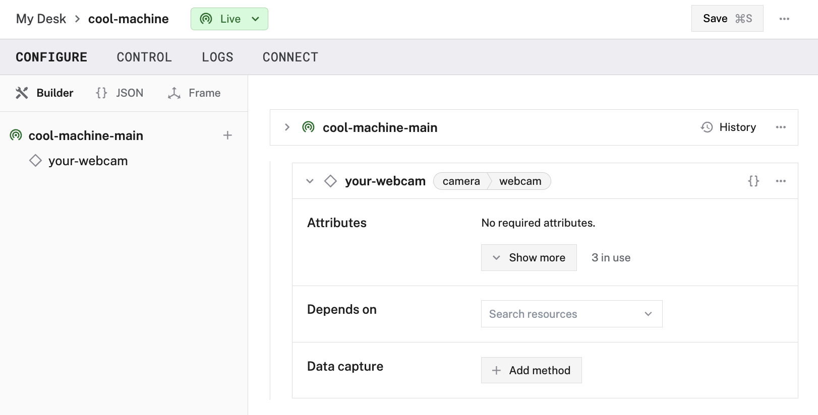
Camera configuration
Add your USB camera as a webcam. Please refer to our webcam documentation for complete instructions.
If you go back to the Control tab and click to expand the base panel, you will see your base and camera:
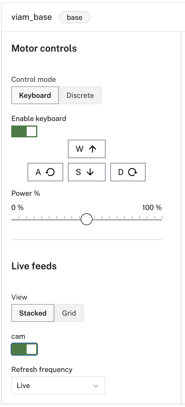
Toggle the switch under Keyboard Disabled to enable keyboard control, then use the W, A, S, and D keys on your keyboard to move your rover around. You can view the camera stream at the same time.
Final config
The full raw JSON config file generated by the configuration steps you just completed will look like this:
If you prefer you can copy paste it, replacing the JSON field on your machine’s CONFIGURE tab instead of going through all the steps above.
Toggling GPIO pin states
The board card in the CONTROL tab provides a way to change the state of the pin connected to the solenoid. If you click the board component, you will be able to see your GPIO pin and its current state. In the Set part of the GPIO section, select pin 37 (the pin we wired to control the solenoid). If you set the pin state to high, the solenoid will actuate. If you set it to low, it should deactivate the solenoid. Since we already assembled the robot, setting pin 37 to high launches your foam dart launcher if its loaded.
Control with the Viam app
Controlling the base
- Navigate to Viam app -> CONTROL tab -> base component
- Enable keyboard controls
- Drive your robot around!
Activating the foam dart launcher
- Make sure your foam dart launcher is loaded and ready to go.
- When you are ready, navigate to the Viam app -> CONTROL tab -> board component and set the IN pin (pin 37 in our example) to high to activate.
You can see the demo video of it in action here:
Troubleshooting
If any component fails to appear when connecting to the robot in the Viam app, check the Logs tab for potential errors.
Summary
In this tutorial, you learned how to create a remotely-controlled foam dart launching robot activated by the GPIO pins on a Raspberry Pi using Viam. You could use this same concept as the basis for a security robot that launches darts at people if they enter your room, a Nerf ball blaster dog toy, a kitten treat shooter for cats to fetch in excitement, you name it! You could even add object detection and machine learning and activate the launcher only when the camera sees a specific object or person.
If you are looking for a new robotics project, check out our other tutorials.You can also ask questions in the Community Discord and we will be happy to help.
