

Tipsy makes it easy to replenish everyone’s drinks at a party. Designed with ultrasonic sensors and cameras, Tipsy is equipped to detect the presence of obstacles and people in its surrounding area. While avoiding the obstacles with the ultrasonic sensor distance measurements, it identifies the people using an ML model and object detection and moves towards them with ease. Tipsy allows people to grab a drink without ever having to leave their spot by bringing a bucket of ice-cold drinks within arm’s reach.This tutorial will teach you how to build your own drink-carrying robot.
Requirements
Hardware
To build your own drink-carrying robot, you need the following hardware:
- Raspberry Pi, with microSD card, set up following the Raspberry Pi Setup Guide.
- Assembled SCUTTLE rover with the motors and motor driver that comes with it.
- T-slotted framing: 4 single 4 slot rails, 30 mm square, hollow, 3’ long. These are for the height of the robot.
- T-slotted framing: 2 single 4 slot rail, 30 mm square, hollow, 12 inches long. These are to create a base inside the robot to securely hold the drink box.
- T-slotted framing structural brackets: 30mm rail height.
- Two ultrasonic sensors
- A 12V battery with charger
- DC-DC converter, 12V in, 5V out
- USB camera
- A box to hold drinks
- Optional: Hook-and-loop tape
- Optional: Acrylic panels to cover the sides
- Optional: 3D printer
Software
To build your own drink-carrying robot, you need the following software:
Wire your robot
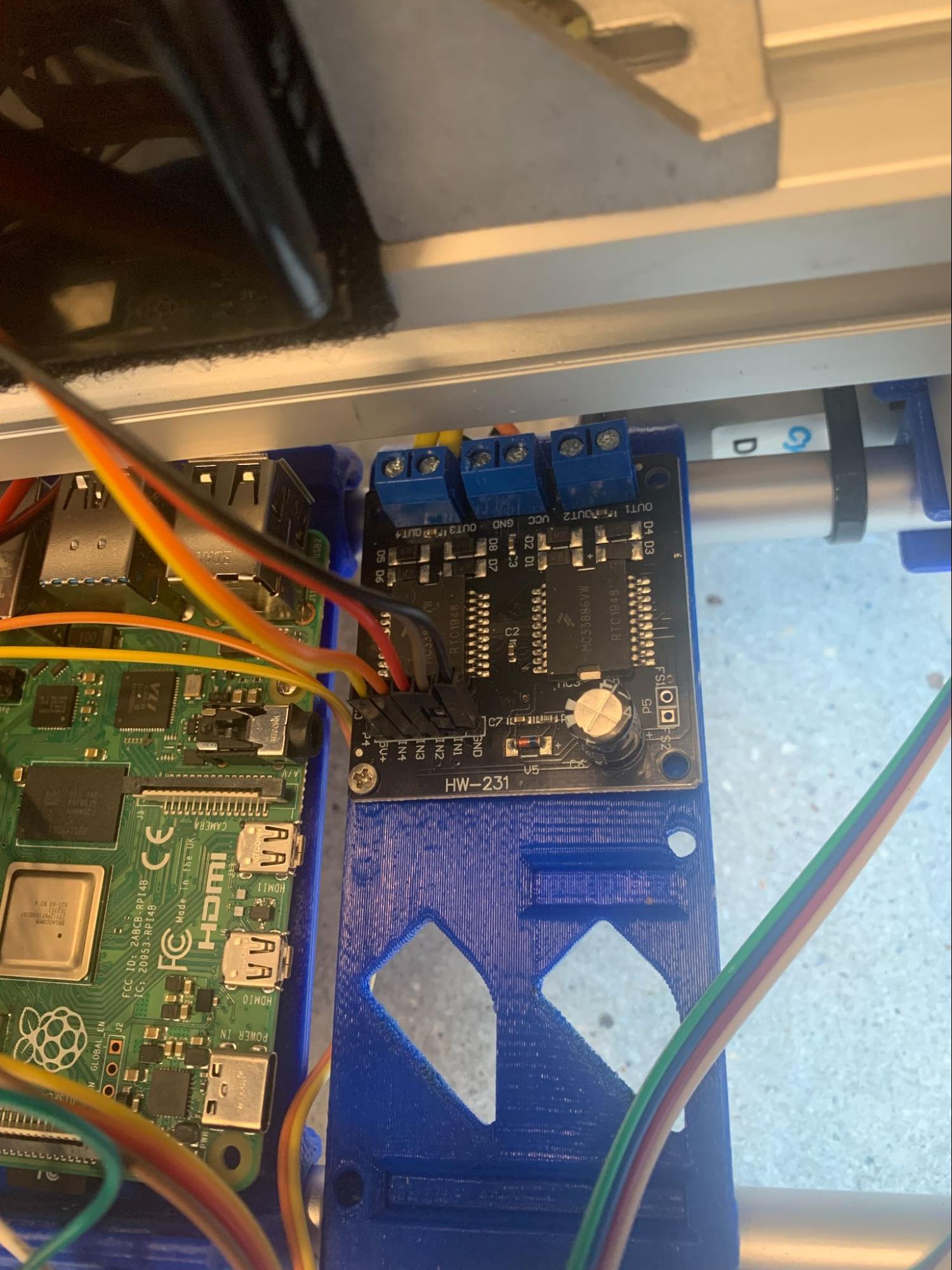
Follow the wiring diagram below to wire together your Raspberry Pi, buck converter, USB camera, motors, motor driver, ultrasonic sensors, and battery:
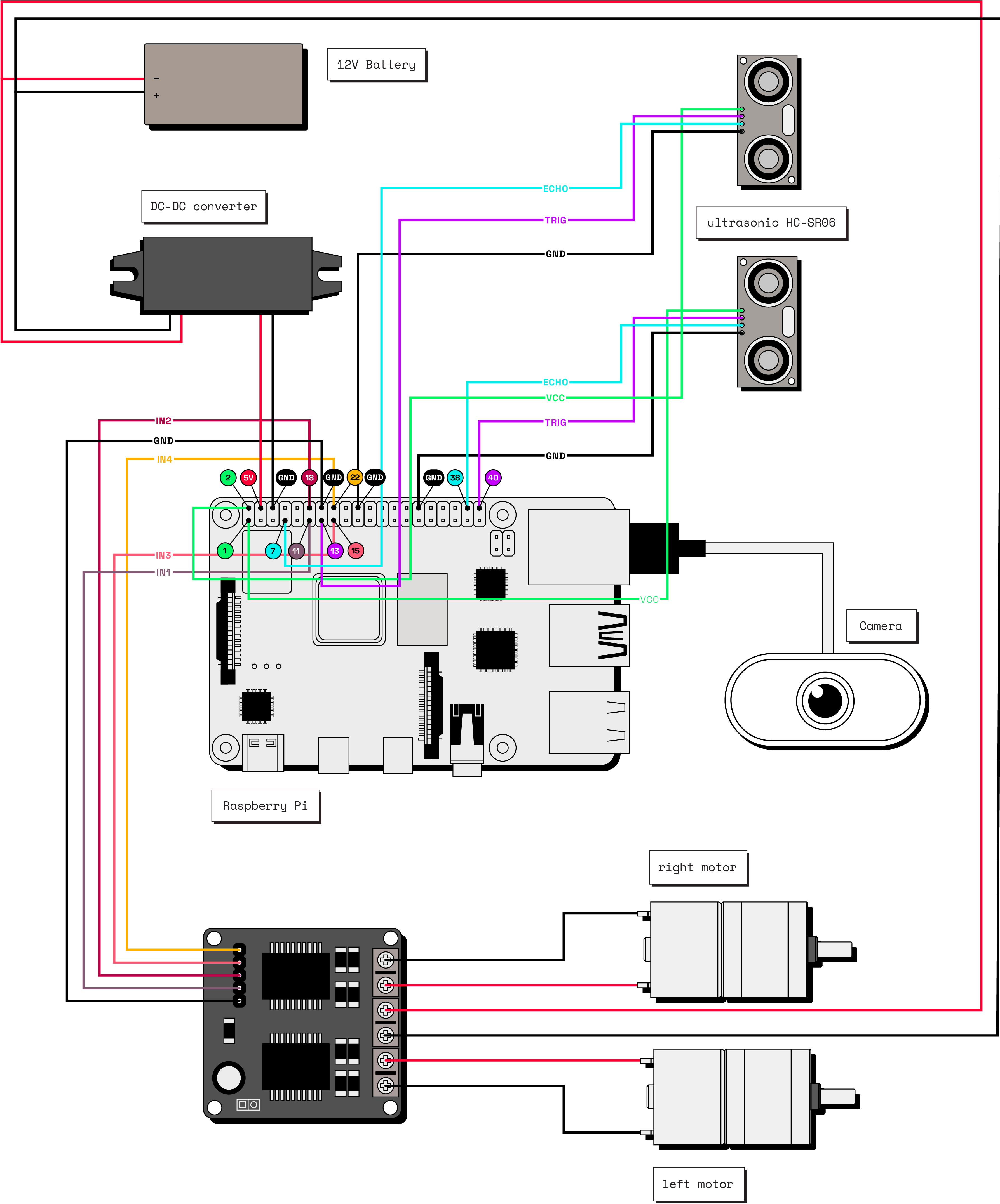
The Tipsy robot uses an assembled SCUTTLE Rover base with some modifications: Tipsy does not use the camera that came with the SCUTTLE Rover because the cable is not long enough to allow the camera to be attached to the top of the robot. Additionally, Tipsy also does not use the encoders or the batteries that come with the kit. These changes are reflected in the wiring diagram.
Configure your components
In the Viam app, add a new machine and give it a name like tipsy. Follow the setup instructions to install viam-server on your Raspberry Pi and connect to your machine.
Navigate to the CONFIGURE tab of your machine’s page in the Viam app.
1. Configure the board
Click the + icon next to your machine part in the left-hand menu and select Component. Select the board type, then select the pi model. Enter local as the name and click Create. Your board component represents the Raspberry P. You can name your board whatever you want as long as you refer to it by the same name in your code.
2. Configure the motors
Click the + icon next to your machine part in the left-hand menu and select Component. Select the motor type, then select the gpio model. Enter rightMotor as the name and click Create.
After clicking Create, a panel will pop up with empty sections for Attributes, Component Pin Assignment, and other information.
In the board dropdown within Attributes, choose the name of the board local to which the motor is wired. This will ensure that the board initializes before the motor when the robot boots up.
Then set Max RPM to 100 and enable direction flip.
In the Component Pin Assignment section, toggle the type to In1/In2. In the dropdowns for A/In1 and B/In2, choose 15 GPIO 22 and 16 GPIO 23 corresponding to the right motor wiring. Leave PWM (pulse-width modulation) pin blank, because this specific motor driver’s configuration does not require a separate PWM pin.
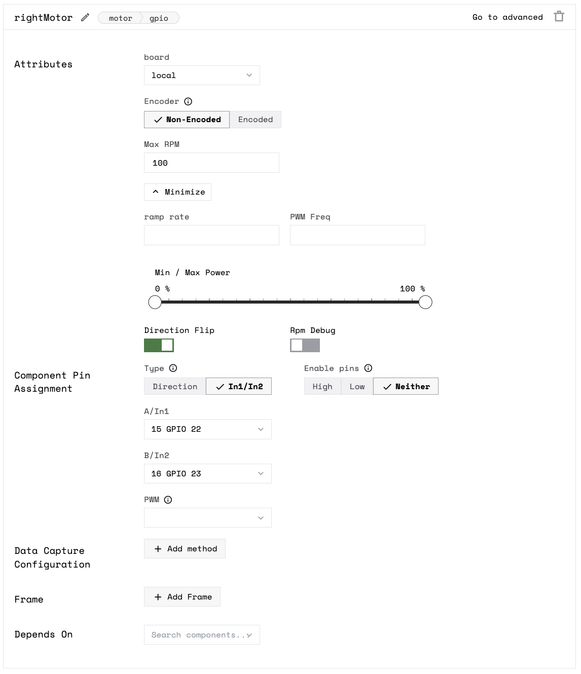
Now let’s add the left motor which is similar to the right motor. Add your left motor with the name “leftMotor”, type motor, and model gpio. Select local from the Board dropdown, set Max RPM to 100, and configure the motors pins as A/In1 and B/In2 corresponding to respectively (according to the wiring diagram), and leave PWM blank.
3. Configure the base
Next, add a base component, which describes the geometry of your chassis and wheels so the software can calculate how to steer the rover in a coordinated way:
Click the + icon next to your machine part in the left-hand menu and select Component. Select the base type, then select the wheeled model. Enter tipsy-base as the name or use the suggested name for your base and click Create.
In the right dropdown, select rightMotor and in the left dropdown select leftMotor. Enter 250 for wheel_circumference_mm and 400 for width_mm. The width describes the distance between the midpoints of the wheels. Add local, rightMotor, and leftMotor to the Depends on field.
4. Configure the camera
Add the camera component:
Click the + (Create) button next to your main part in the left-hand menu and select Component. Start typing “webcam” and select camera / webcam. Give your camera a name. This tutorial uses the name cam in all example code. Click Create.
In the configuration panel, click the video path dropdown and select the webcam you’d like to use for this project from the list of suggestions.
Select the camera you want to use. If you are unsure which camera to select, select one, save the configuration, and go to the Control tab to confirm you can see the expected video stream.
Then make it depend on local so it initializes after the board component.
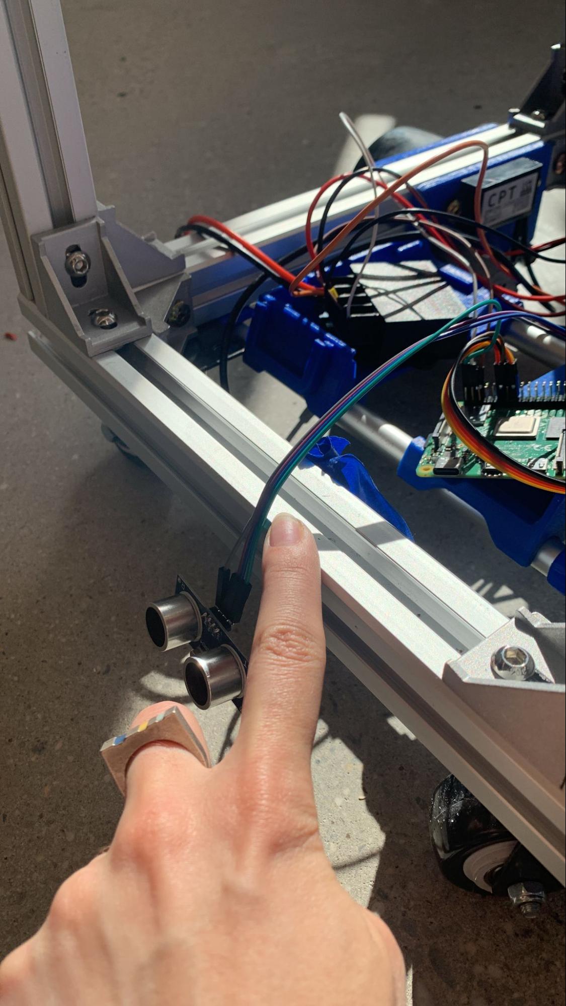
5. Configure the ultrasonic sensors
Add a sensor component:
Click the + icon next to your machine part in the left-hand menu and select Component. Select the sensor type, then select the ultrasonic model. Enter ultrasonic as the name and click Create.
Then fill in the attributes: enter 38 for echo_interrupt_pin and 40 for trigger_pin, according to the wiring diagram. Enter local for board.
You have to configure the other ultrasonic sensors. For each of the additional ultrasonic sensors, create a new component with a unique name like ultrasonic2 (where “2” indicates it’s the second sensor), type sensor, and model ultrasonic. In the attributes textbox, fill in the trigger_pin and echo_interrupt_pin corresponding to the pins your ultrasonic sensors are connected to.
While this tutorial and associated code demonstrates using 2 ultrasonic sensors, the production Tipsy uses 5 in total: two up top underneath the drink box, two on the sides of the robot, and one at the bottom. This provided adequate coverage for use around our office. You can change the amount based on your preference.
Test your components
With the components configured, navigate to the Control tab. On the control tab, you will see panels for each of your configured components.
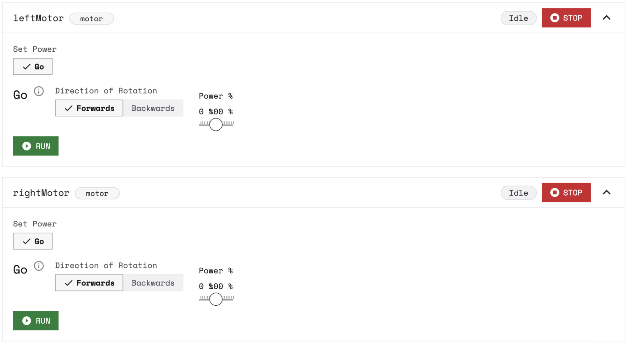
1. Motors
Click on both motor panels and check that they run as expected by clicking RUN.
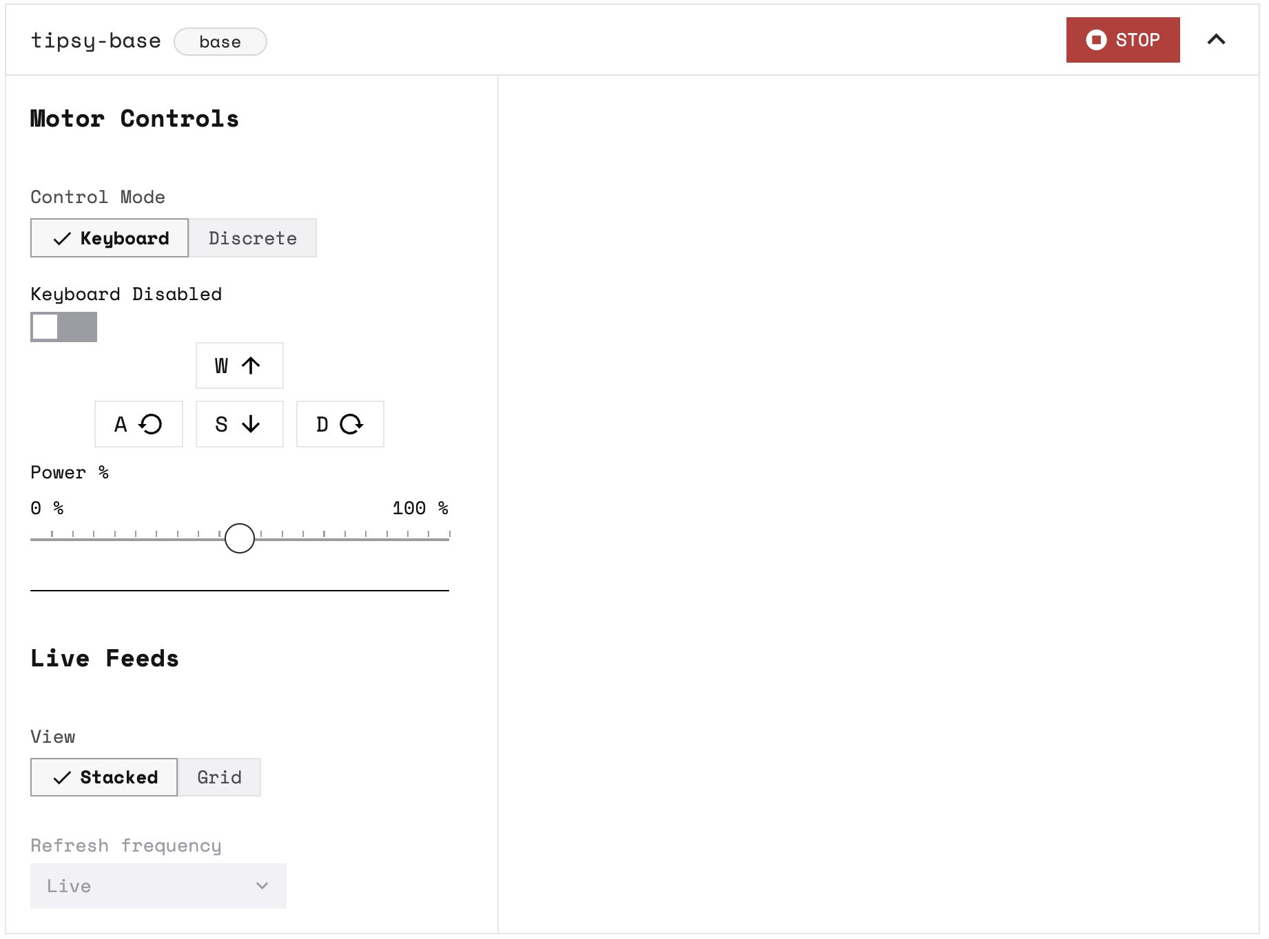
2. Base
Click on the base panel and enable the keyboard. Then move your rover base around by pressing A, S, W, and D on your keyboard.
You can also adjust the power level to your preference.
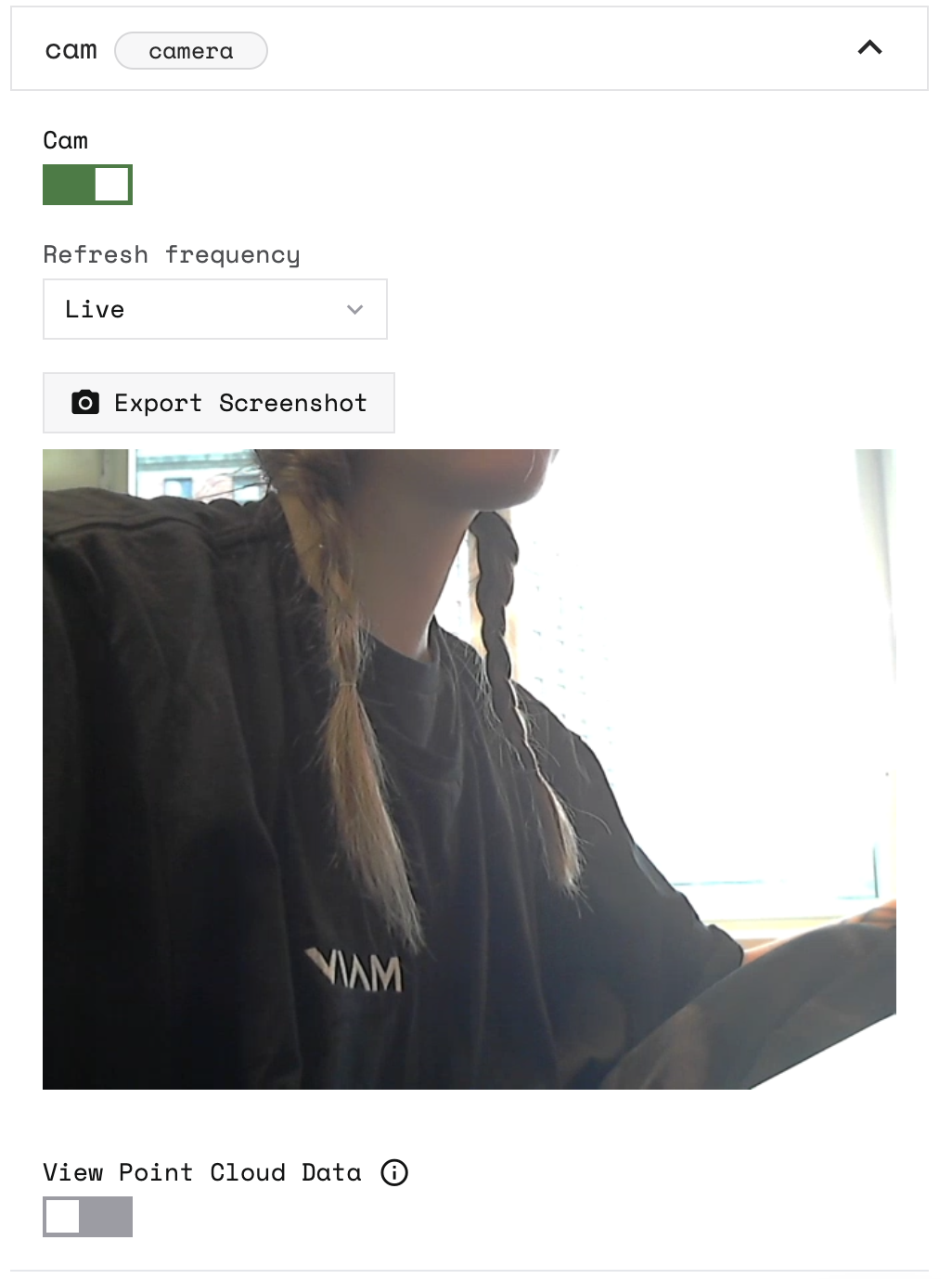
3. Camera
To see your camera working, click on the camera panel and toggle the camera on.
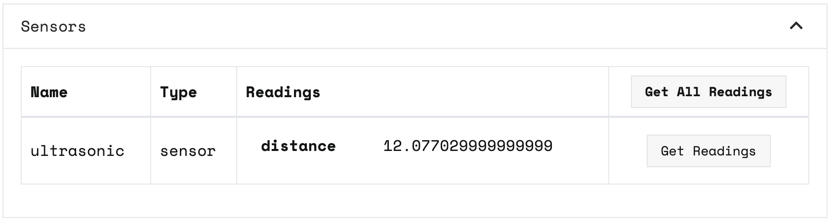
Ultrasonic Sensors
Click on your ultrasonic sensors panels and test that you can get readings from all of them.
Click Get Readings to get the distance reading of the sensor.
Configure your services
Now that you know your copmonents are configured and working, it is time to add computer vision by configuring the vision service on your machine. This tutorial uses a pre-trained Machine Learning model from the Viam Registry called EfficientDet-COCO. The model can detect a variety of things, including Persons. You can see a full list of what the model can detect in labels.txt file.
If you want to train your own model instead, follow the instructions in train a model.
1. Configure the ML model service
Navigate to your machine’s CONFIGURE tab.
Click the + (Create) button next to your main part in the left-hand menu and select Service. Start typing ML model and select ML model / TFLite CPU from the builtin options.
Enter people as the name, then click Create.
In the new ML Model service panel, configure your service.

Select Deploy model on machine for the Deployment field. Then select the viam-labs:EfficientDet-COCO model from the Models dropdown.
2. Configure an ML model detector vision service
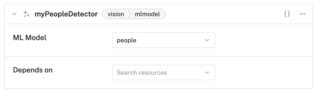
Click the + (Create) button next to your main part in the left-hand menu and select Service. Start typing ML model and select vision / ML model from the builtin options.
Enter myPeopleDetector as the name, then click Create.
In the new vision service panel, configure your service.
Select people from the ML Model dropdown.
3. Configure the detection camera
To be able to test that the vision service is working, add a transform camera which will add bounding boxes and labels around the objects the service detects.
Click the + (Create) button next to your main part in the left-hand menu and select Component. Start typing “webcam” and select camera / transform. Give your transform camera the name detectionCam and click Create.
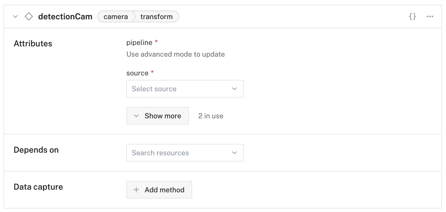
In the new transform camera panel, click on {} to go to advanced mode and replace the attributes JSON object with the following object which specifies the camera source that the transform camera will use, and defines a pipeline that adds the defined myPeopleDetector:
It is good practice to also add your camera cam as a dependency in the Depends on section, to ensure the components are loaded in the correct order.
Click Save in the top right corner of the screen.
![detectionCam component panel with type camera and model transform, Attributes section filled with source and pipeline information.]](https://cdn.prod.website-files.com/62fba5686b6d47653f1ed2ae/66eaf86cf8fab2e212ec31df_66229b412198a25639ea15fb_app-detection-after.png)
Test your detection camera
Now you can test if the detections work. Navigate to the Control tab and click on the detectionCam panel. Toggle the camera on to start the video stream.
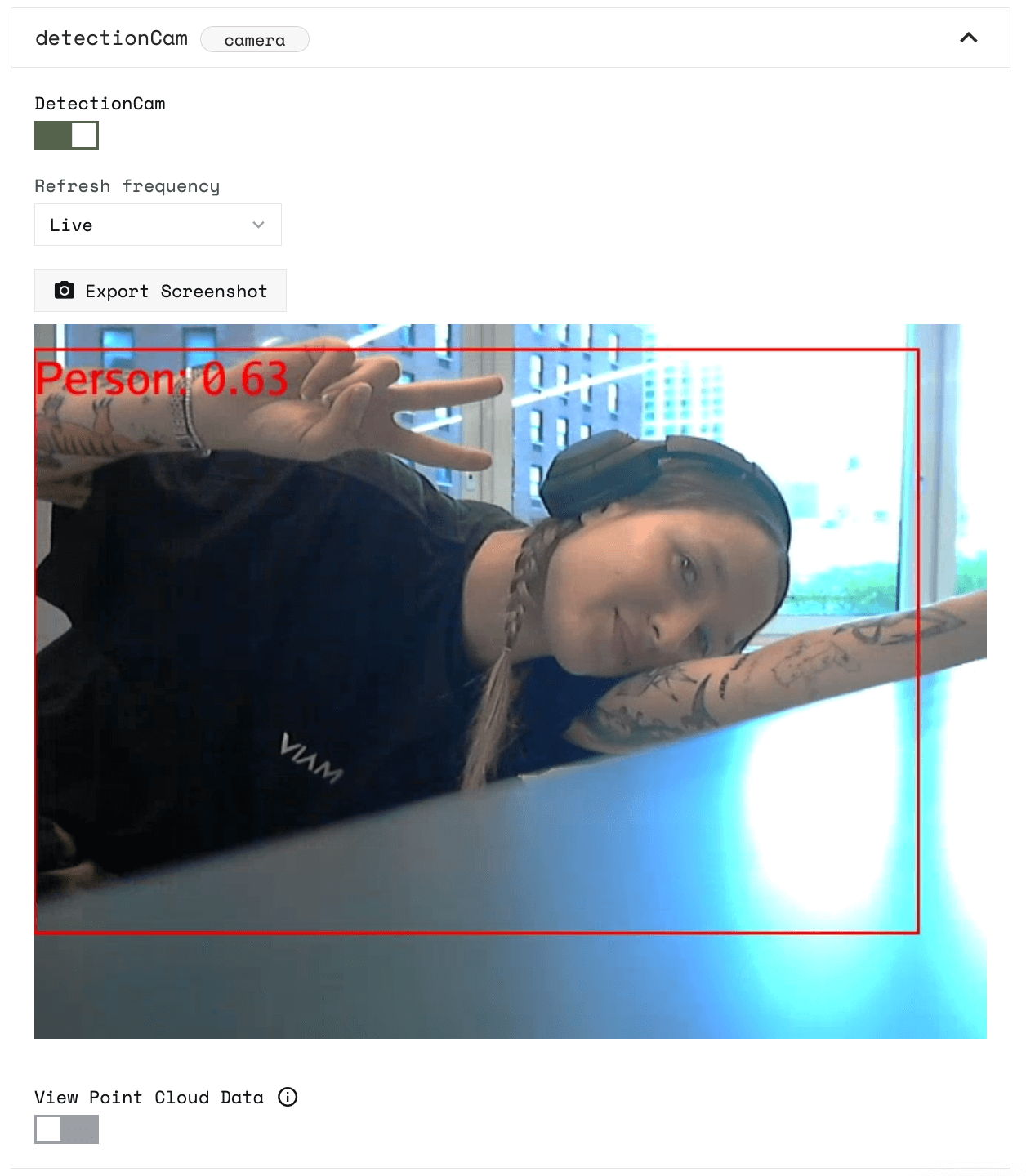
You can also see your physical camera stream and detection camera stream together on the base panel.
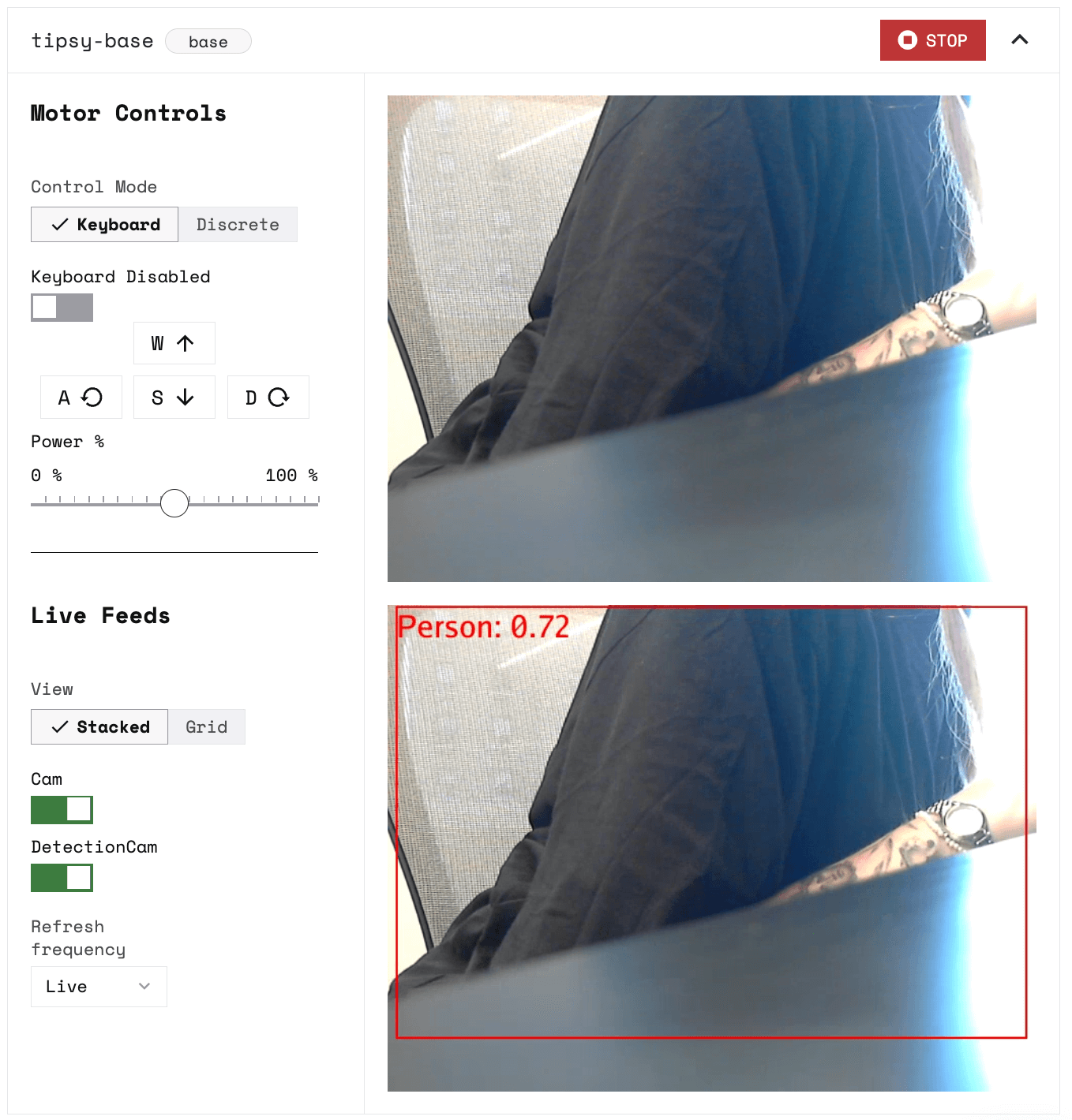
At this point, it is a simple detection camera: it will detect any object in the label.txt file. When we write the code for the robot, we can differentiate between, say, a person or a chair.

Design your robot
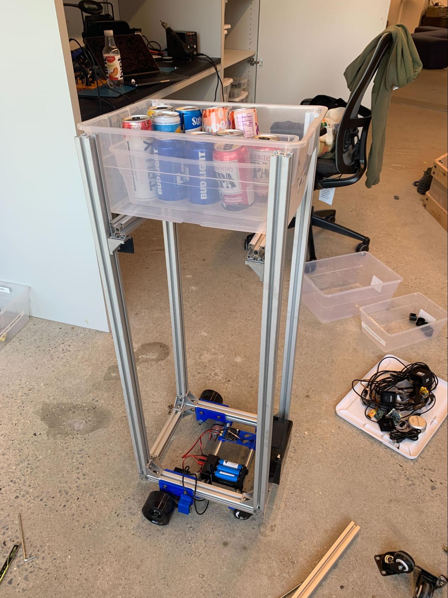
Now that you have all your components wired, configured, and tested, you can assemble your robot.
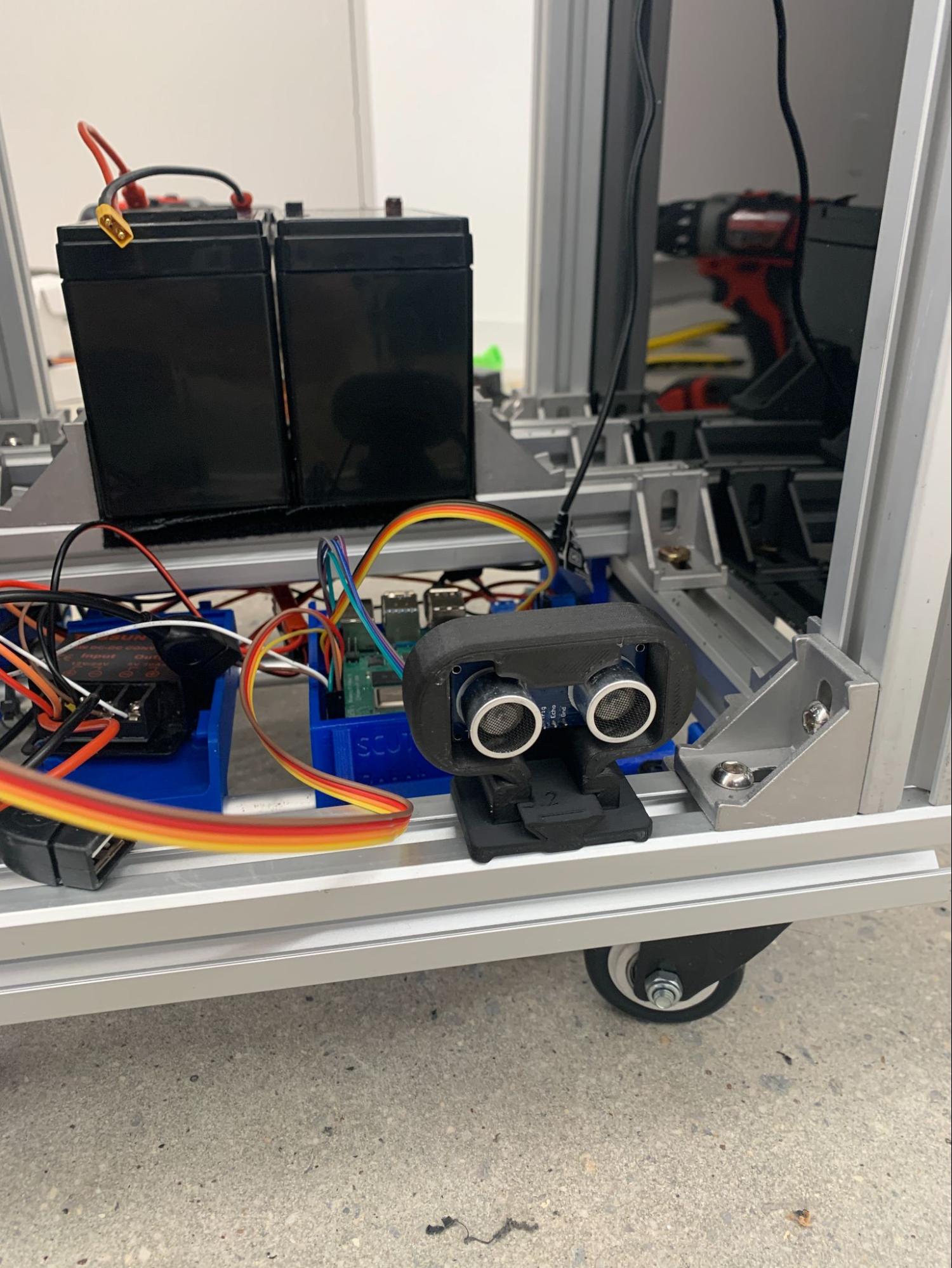
Add four 3’ long T-slotted framing rails along the corners of the SCUTTLE Rover base to make it a tall structure. Then add two 12 inches long T-slotted framing rails in the middle of the structure at the height that you want to hold the box. Secure them using T-slotted framing structural brackets.
Next, add the wired Raspberry Pi, motor driver, and 12V battery to the base.
You can use the 3D-printed holders that come with the assembled SCUTTLE base for the Raspberry Pi and the motor driver. You can also print holders based on SCUTTLE designs from GrabCAD.
Secure the 12V battery to the bottom using hook-and-loop tape or other tape, and secure the sides using T-slotted brackets.
Secure the buck converter with hook-and-loop tape, double-sided tape, or a 3D printed holder.
Use hook-and-loop fasteners or something else to secure the USB camera to the box that holds the drinks so it faces the front, towards any people who may interact with the robot.
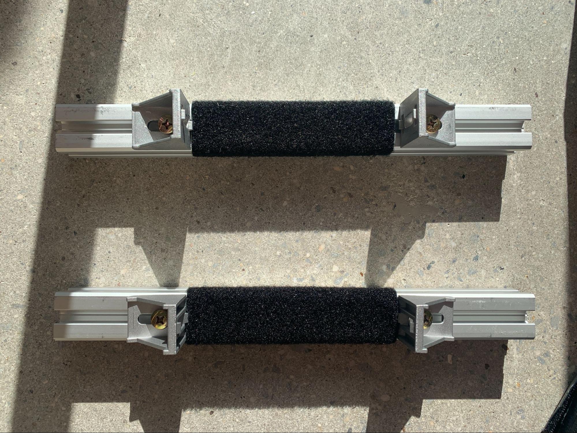
For ultrasonic sensors to fit the framing, we recommend 3D printing enclosures. This step is optional but makes the project look more aesthetically pleasing and ensures that the sensors don’t fall out as your robot moves around.
You can design your own enclosure, or you can use the SCUTTLE design we used, a 3D-printed enclosure with a twist bracket that fits the rails:
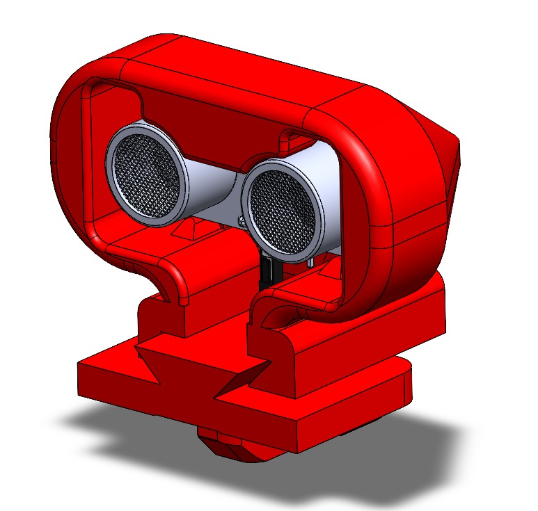
The STL files we used can be found in our project repository.
If you decide not to use a 3D printer, you can tape the ultrasonic sensors to the rails. We recommend that you do so within the enclosure, perhaps under the drink box and above the rover base, so they don’t touch people or obstacles as the robot moves around, as this could cause them to fall off or get damaged.
Now we are ready to make Tipsy look pretty! Optionally, add acrylic side panels and cover the electronics.
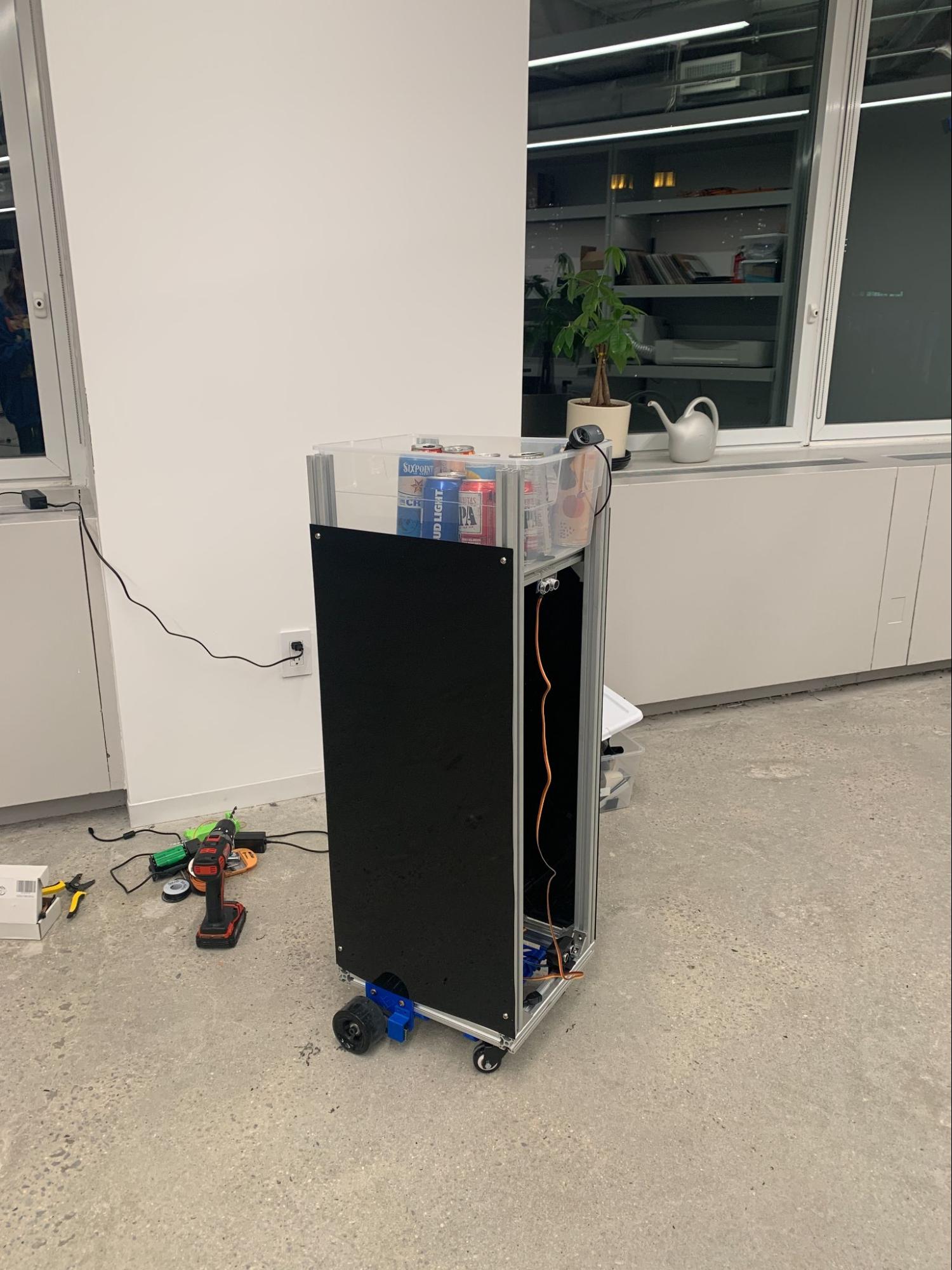
We drilled and screwed the panels onto the railing. You can also use a laser cutter to cut them into the sizes you prefer if you want different side panels.
Add the robot logic
Download the full code onto your computer.
Let’s take a look at what it does. First, the code imports the required libraries:
Then it connects to our robot using a machine part API key and address. Replace these values with your machine’s own location secret and address, which you can obtain from the Code sample tab:
CAUTION: Do not share your API key or machine address publicly. Sharing this information could compromise your system security by allowing unauthorized access to your machine, or to the computer running your machine.
Next, the code defines functions for obstacle detection. The first method, obstacle_detect(), gets readings from a sensor, which is used by the second method, gather_obstacle_readings(), to gather all the distance readings from a list of sensors. Lastly, the third method, obstacle_detect_loop(), uses an infinite loop to periodically check the readings to stop the base if it’s closer than a certain distance from an obstacle:
Then, we define a person detection loop, where the robot is constantly looking for a person, and if it finds the person, it goes toward them as long as there are no obstacles in front. If it doesn’t find a person, it will continue looking by rotating the robot base 45 degrees at a time and looking again.
Lines 12 and 13 are where it checks specifically for detections with the label Person and not every object in the labels.txt file:
Finally, the main() function initializes the base, the sensors, and the detector. It also creates two background tasks running asynchronously, one looking for obstacles and avoiding them (obstacle_task), and one looking for people and moving towards them (person_task):
When you run the code, you should see results like this:
Summary
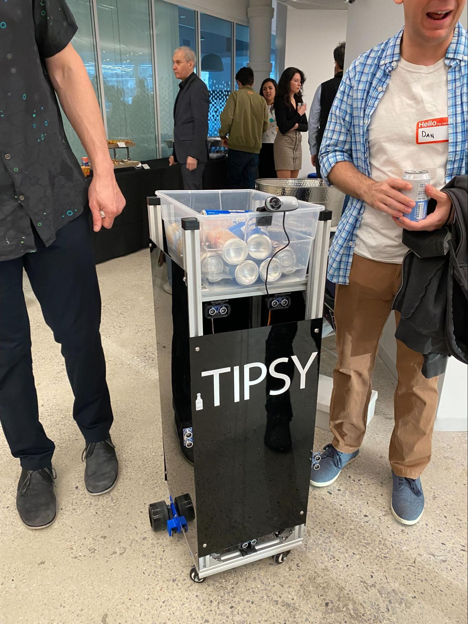
In this tutorial, you learned how to make your own drink-carrying robot. You no longer have to interrupt your conversations or activities just to grab another drink. Overall, Tipsy is the ultimate drink buddy for any social event. With its people detection and obstacle avoidance technology, convenient autonomous operation, and modern design, it’s sure to impress all your guests.
To make Tipsy even more advanced, you can try to:
- Add more ultrasonic sensors so it doesn’t hit objects at different heights, you can also attach them to a moving gantry along the side rails
- Add a depth camera to detect obstacles and how close they are to Tipsy
- Add an IMU to see if Tipsy is tipping backward
- Add a lidar
You can also design another robot for collecting the empty drink cans, or a bartender robot with pumps that can mix some drinks. Until then, sit back, relax, and let Tipsy handle the drink-carrying duties for you!
For more robotics projects, check out our other tutorials.
Have questions, or want to meet other people working on robots? Join our Community Discord.
